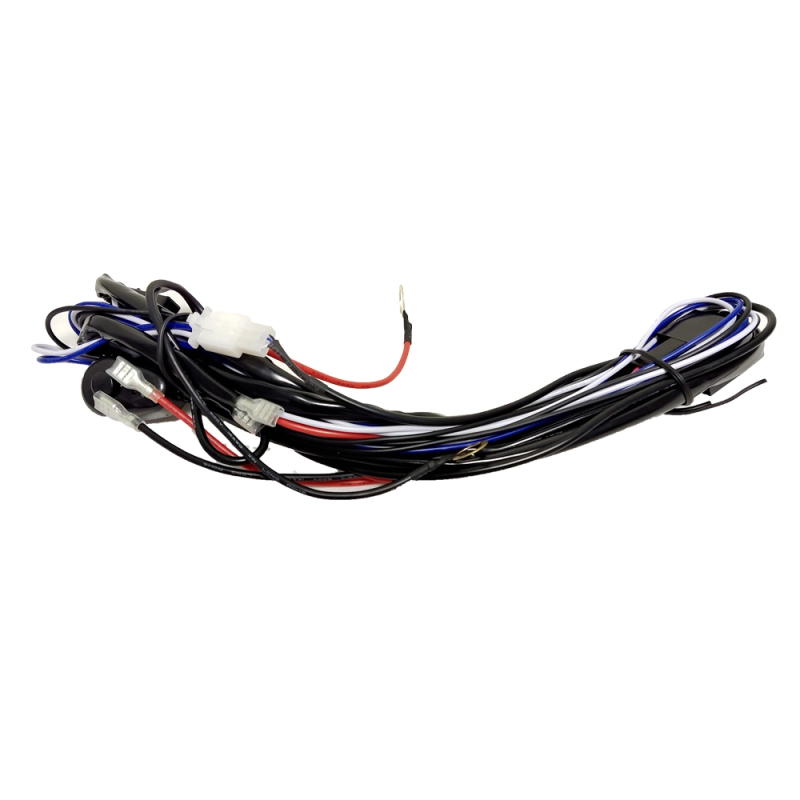
Installing aftermarket electrical accessories carries high stakes. Modern vehicle electrical systems, especially those relying on CAN bus architecture, are highly sensitive to voltage changes and unexpected current draws. Improper installation often leads to parasitic power drains, melted insulation, premature component failure, or catastrophic electrical fires. Adding high-draw accessories requires completely isolating the new circuit from the factory system. This prevents overloading OEM wiring and protects your vehicle warranty.
This guide serves as a definitive, technical roadmap for evaluating harness specifications, mitigating installation risks, and executing a professional-grade custom wiring harness installation. We will cover the exact formulas for wire gauge selection, the mechanical differences in conductor metallurgy, and the step-by-step procedures required to build a reliable, weather-sealed electrical circuit that performs flawlessly under harsh automotive conditions.
Component Isolation is Mandatory: A dedicated relay and inline fuse are non-negotiable for protecting the vehicle’s factory electrical architecture from high-amperage aftermarket accessories.
Specification Dictates Safety: Wire gauge (AWG) must be mathematically matched to the total amperage draw and wire run length to prevent voltage drop and thermal events.
Conductor Metallurgy Matters: Oxygen-Free Copper (OFC) must be prioritized over Copper-Clad Aluminum (CCA) to ensure long-term conductivity, flexibility, and corrosion resistance.
Termination Quality Equals Reliability: Weather-sealed connections (heat-shrink crimps or soldered joints) and proper loom routing are the primary differentiators between a reliable installation and a premature failure.
Application-Specific Selection: The architectural requirements for an Automotive Light Bar Wiring Harness differ significantly from a Car Headlight Wiring Harness in terms of switching logic, continuous duty ratings, and integration with factory signal wires.
Evaluating Your Custom Wiring Harness Requirements
Success Criteria: Amperage, Gauge, and Relay Specifications
Calculating the total circuit load dictates every subsequent hardware choice. You must determine the exact amperage your accessory will draw. Use the standard formula: Watts divided by Volts equals Amps. For example, a 300-watt light bar operating on a standard 12-volt automotive system draws 25 amps. Knowing this exact draw allows you to select the correct wire gauge to prevent voltage drop over the length of the wire run.
A continuous-duty relay acts as an electromagnetic switch. It uses a low-current signal from the cabin switch to close a high-current circuit directly from the battery. Standard automotive relays are typically rated for 40A or 60A. This architecture keeps dangerous high current out of the passenger cabin and ensures the accessory receives full alternator voltage.
Amperage Load
Recommended AWG (10-15 ft run)
Recommended AWG (15-20 ft run)
Typical Application
0 - 10 Amps
16 AWG
14 AWG
Small LED pods, interior lighting, trigger wires
10 - 20 Amps
14 AWG
12 AWG
Medium light bars, standard horns, small pumps
20 - 30 Amps
12 AWG
10 AWG
High-output lighting, air compressors, audio amps
30 - 40 Amps
10 AWG
8 AWG
Cooling fans, large multi-row light bars, winches
40 - 60 Amps
8 AWG
6 AWG
Heavy-duty compressors, primary distribution blocks
Conductor Metallurgy: OFC vs. CCA
Oxygen-Free Copper (OFC) provides superior electrical conductivity and mechanical durability under high vibration. It is the standard for professional automotive wiring. Copper-Clad Aluminum (CCA) has higher electrical resistance, meaning it carries less current for the same physical wire size. CCA is highly susceptible to galvanic corrosion in wet environments. Once moisture penetrates the insulation, the aluminum core oxidizes rapidly, turning into a white powder. This leads to severe voltage drops, excessive heat generation, and eventual circuit failure.
Relay Architecture: SPST vs. SPDT and Diode Protection
Single Pole Single Throw (SPST) relays control a single circuit, turning it on or off. They have four pins: power in, power out, ground, and trigger. Single Pole Double Throw (SPDT) relays have five pins and toggle power between two separate circuits, useful for high/low beam applications. When a relay coil de-energizes, the collapsing magnetic field creates a high-voltage spike called inductive kickback. Diode-suppressed or resistor-suppressed relays absorb this spike. This protection is mandatory to prevent damage to sensitive vehicle ECUs when tapping into factory trigger wires.
Connector Standards and Ingress Protection (IP Rating)
Engine bays expose electrical connections to water, dirt, road salt, and extreme heat. Using IP67 or IP68-rated connectors prevents moisture ingress and terminal corrosion. Deutsch DT/DTP series, Weather Pack, and Metri-Pack connectors utilize silicone seals and precise terminal locking mechanisms to guarantee environmental protection. Standard unsealed spade terminals will corrode within months if exposed to the elements, leading to high resistance and intermittent operation.
Solution Categories: Pre-Built vs. Scratch-Built Harnesses
Purchasing a pre-terminated harness saves time and ensures baseline functionality for standard accessories. It is a plug-and-play solution for simple installations. Building one from bulk wire allows for exact length routing, customized switch integration, and specific connector choices. Scratch-built solutions require more upfront investment in specialized crimping tools and bulk materials but yield a cleaner, OEM-equivalent fit in complex engine bays without coils of excess wire zip-tied to the fender.
Pre-Installation: Tools, Safety, and Risk Mitigation
Essential Diagnostic and Installation Tools
Professional installations require specific tools to ensure reliability. You need a high-impedance Digital Multimeter (DMM) for testing voltage and continuity. Ratcheting wire crimpers for both open and closed-barrel terminals ensure a cold-weld connection. You also need quality wire strippers, a heat gun with a reflector nozzle, terminal depinning tools, and fish tape for firewall routing. Required consumables include dielectric grease, high-temp TESA tape for engine bay routing, corrugated split loom, heavy-duty zip ties, and marine-grade adhesive-lined heat shrink tubing.
Mitigating Electrical Risks (The Disconnect Protocol)
Always disconnect the negative battery terminal before beginning any electrical work. This strict protocol prevents accidental short circuits against the vehicle chassis while routing live wires. Your fusing strategy is equally critical. Locate the inline fuse as close to the battery positive terminal as physically possible, ideally within 12 inches. This placement protects the maximum length of wire from dead shorts. If the wire chafes against the chassis downstream of the fuse, the fuse blows. If it chafes upstream of the fuse, you risk an electrical fire.
CAN-Bus and Sensitive ECU Safety
Tapping directly into factory wires on CAN-bus equipped vehicles carries significant risk. Splicing into data lines can alter circuit resistance, corrupt data streams, and log fault codes. Identify safe ignition-switch trigger sources using a high-impedance DMM. Never use a low-impedance incandescent test light, as it can draw enough current to fry sensitive solid-state modules. Always use a dedicated fuse tap or a factory-provided auxiliary upfitter wire if available.
Step-by-Step Custom Wiring Harness Installation
Step 1: Component Placement and Routing Strategy
Effective routing prevents mechanical damage and electrical interference. Avoid high-heat areas like exhaust manifolds, turbochargers, and EGR valves. Keep wires away from moving parts such as steering shafts, suspension components, or serpentine belts. Keep wires away from sharp metal edges. Sleeve all wires in high-temp TESA tape or braided loom before routing. Utilize existing factory wire channels and firewall grommets to maintain a clean, OEM-equivalent appearance. Secure the loom every 8 to 12 inches with zip ties to prevent vibration chafing.
Step 2: Mounting the Relay and Inline Fuse
Select a relay mounting location high on the firewall or inner fender, away from direct moisture spray and road debris. Orient the relay with the pins facing downward to prevent water from pooling inside the housing. Secure the fuse holder firmly using a bolt or heavy-duty zip ties; do not let it hang loose by the wires. Connect the primary power ring terminal directly to the battery positive post or an established auxiliary power distribution block. Ensure the ring terminal is sized correctly for the mounting stud to ensure maximum surface area contact.
Step 3: Terminating Connections and Connector Assembly
Mechanical crimping is preferred in high-vibration automotive environments. Soldering can create brittle heat-affected zones in the wire that are prone to cracking under vibration. Follow these steps for assembling a weatherproof connection:
Strip exactly 1/4 inch of insulation from the wire end, ensuring no copper strands are cut.
Insert the stripped wire into the terminal barrel, ensuring the insulation butts up against the terminal.
Crimp the terminal using a ratcheting crimper designed for that specific terminal type (e.g., W-crimp for open barrel).
Perform a physical pull test by tugging firmly on the wire to verify mechanical retention.
Insert the pinned wire into the rear of the connector housing until you hear a distinct click.
Insert the wedgelock into the front of the connector to lock the pins in place.
Slide a piece of marine-grade, adhesive-lined heat shrink over the rear of the connector and wire, then shrink it with a heat gun to provide structural strain relief and complete environmental sealing.
Step 4: Integrating the Switch (Cabin Penetration)
Pass the low-current switch wires through the factory firewall grommet safely using fish tape. Avoid piercing existing factory wiring. Cut a small slit in the rubber grommet, push the fish tape through, tape your wires to the end, and pull them into the cabin. Wire the cabin switch by utilizing an add-a-circuit fuse tap on an ignition-switched fuse slot. This provides power for switch illumination and ensures the accessory cannot drain the battery when the vehicle is turned off. Ground the switch locally to a clean metal point under the dashboard.
Specific Application Nuances and Scalability
Installing an Automotive Light Bar Wiring Harness
High-wattage LED bars demand robust infrastructure. An Automotive Light Bar Wiring Harness often requires 12 AWG or 10 AWG OFC wire and high-capacity 60A relays to handle continuous loads without overheating. Multi-zone or dual-color light bars require complex switching logic. A standard Car Light Bar Wiring Harness might need multi-pole switches or multi-pin Deutsch connectors, such as the DT 4-pin, to control independent lighting zones (e.g., amber backlighting vs. main white driving beam).
Upgrading a Car Headlight Wiring Harness
Factory headlight wiring is often thin, causing voltage drops that dim halogen or HID bulbs. Upgrading to a dedicated Car Headlight Wiring Harness bypasses the factory headlight switch paths. It delivers full alternator voltage directly to the bulbs from the battery. This harness uses the OEM headlight connector merely as a low-current trigger signal for the new relay. For vehicles with PWM (Pulse-Width Modulation) headlight systems, you must integrate anti-flicker decoders or capacitors across the trigger wires to prevent relay chatter and strobe effects.
Post-Installation Testing and Troubleshooting
Multimeter Verification and Voltage Drop Testing
Test the circuit before applying a load. Perform continuity testing and open-circuit voltage verification at the accessory connector. Once the accessory is connected and powered, perform a voltage drop test across the new harness to verify connection integrity.
Set your DMM to DC Volts.
Turn on the accessory so current is flowing through the circuit.
Place the positive probe on the battery positive post and the negative probe on the positive terminal at the accessory.
Read the voltage displayed; this is the voltage lost across the positive side of the circuit.
Repeat the process for the ground side by placing the negative probe on the battery negative post and the positive probe on the accessory ground terminal.
An acceptable voltage drop is typically less than 0.2V on critical connections, with a maximum of 0.5V across the entire circuit.
Parasitic Draw Diagnostic Protocol
Verify that the newly installed harness does not drain the battery while the vehicle sits. Set your DMM to the milliamp (mA) scale and place it in series with the negative battery cable. Ensure the accessory switch and vehicle ignition are in the "off" position, and all doors are closed. Wait 15 minutes for the vehicle modules to go to sleep. The current draw should remain at the vehicle's factory baseline (usually under 50mA), confirming the relay is fully open and the switch illumination is not pulling standby power.
Common Failure Points and Diagnostic Framework
Post-installation failures usually stem from three specific issues: bad chassis ground connections due to paint or rust, blown inline fuses caused by pinched wires, and relays clicking without delivering power. If the relay clicks but the accessory fails to power on, check the primary power feed from the battery. Verify the inline fuse is intact. Then, verify the integrity of the ground connection at the accessory. A high-resistance ground will prevent the accessory from operating even if full voltage is present on the positive side.
Conclusion
Treating a wiring installation as a structural upgrade rather than a cosmetic accessory is critical for vehicle safety and reliability. Cutting corners on wire metallurgy, wire gauge, or termination quality guarantees eventual failure. When selecting components, prioritize pure copper wire, sealed relays, appropriate AWG for your specific load, and IP-rated weatherproof connectors.
Calculate your total amperage draw before purchasing any wire or relays.
Source OFC wire and IP67-rated connectors for all exterior connections.
Map out your routing path to avoid heat sources and moving parts.
Perform a voltage drop test immediately after installation to verify connection integrity.
FAQ
Q: Can I use CCA wire instead of OFC for my light bar?
A: It is highly discouraged. Copper-Clad Aluminum (CCA) has higher resistance, generates more heat, and corrodes rapidly in automotive environments. Always use Oxygen-Free Copper (OFC) for reliable power delivery.
Q: Why does my relay click rapidly when I turn on my headlights?
A: Rapid clicking, or relay chatter, usually occurs in vehicles with Pulse-Width Modulation (PWM) electrical systems. You need to install an anti-flicker capacitor or decoder to smooth the pulsed voltage into a steady signal.
Q: Where is the best place to ground my new harness?
A: The best ground is directly to the negative battery terminal. If that is not possible, ground to a clean, unpainted factory chassis ground point. Sand away any paint or rust to ensure bare metal contact.
Q: Do I really need a relay if my switch is rated for 20 amps?
A: Yes. Running high current through the firewall and into the passenger cabin switch creates a severe fire hazard. A relay keeps the high-amperage power isolated in the engine bay.
Q: How close should the inline fuse be to the battery?
A: The inline fuse should be installed as close to the positive battery terminal as physically possible, absolutely within 12 inches. This protects the maximum length of the wire run from a short circuit.
Shenzhen Creek Optoelectronic Technologies Co., Ltd. produce Car LED work lights, off-road LED light bar, forklift safety lights, agricultural tractor work lights, LED strobe and beacon lights, car radios, etc.