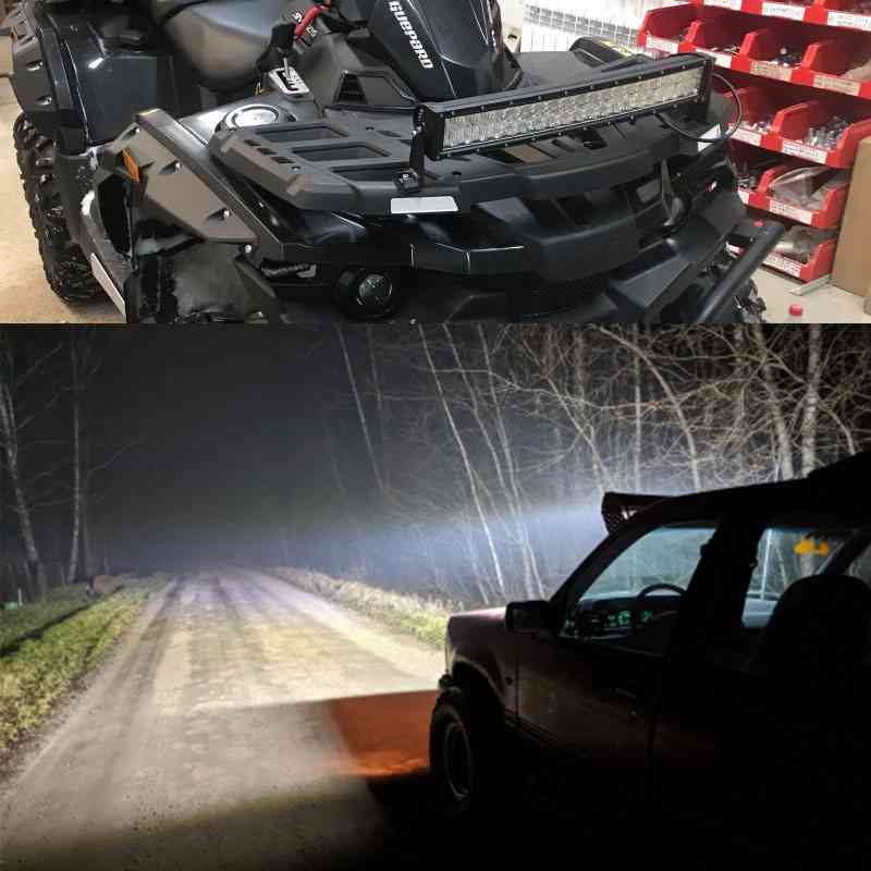
Aftermarket lighting installations often fail because of incorrect electrical load calculations, mismatched voltage specifications, and overloaded multi-channel controllers. Roof-mounted lighting setups demand long wire runs across the vehicle cabin. These extended runs increase the risk of severe voltage drop, melted wiring harnesses, and diminished lumen output. You must align the operating voltage and wire gauge perfectly with your vehicle’s native electrical architecture. This risk multiplies when you integrate multi-function features like combo beams or amber accents into a single housing.
A standard curved Led light bar requires precise electrical planning. We will establish a technical evaluation framework to determine your exact requirements. You will learn how to evaluate amp draw, vehicle type, controller limits, and installation distance. This data determines whether your specific application demands a dedicated 12-volt, 24-volt, or dual-voltage lighting system.
Amp Draw Dynamics: Operating a curved LED light bar on a 24V system halves the amperage draw compared to a 12V system, significantly reducing stress on relays, wiring, and the vehicle's alternator.
Wire Gauge Scaling: Selecting the correct American Wire Gauge (AWG) is entirely dependent on the specific voltage, total wattage, and the physical length of the wiring harness.
Dual-Voltage Flexibility: Modern dual row 12V 24V LED light bar systems utilize internal step-down converters, allowing seamless integration across diverse vehicle fleets without stocking multiple SKUs.
Voltage Drop Mitigation: Long cable runs (common in roof-mounted curved bars) require strict adherence to voltage drop limits (<3%) to prevent premature diode degradation.
Multi-Channel Management: Advanced light bars with wide flood, long-range spot, and accent lighting require careful per-channel amperage calculations to avoid overloading switches and controllers.
Understanding Voltage Dynamics in a Curved LED Light Bar
You must first establish an accurate electrical baseline before cutting any wire or mounting any brackets. A high-output lighting system does not inherently produce more lumens at 24 volts than it does at 12 volts. The actual light output remains identical assuming the wattage rating is the same. The difference lies entirely in electrical efficiency, thermal management within the wiring harness, and the reduced tax on the host battery system. Higher voltage allows for lower current, which fundamentally changes how you design the installation circuit.
Ohm’s Law and Amp Draw Calculations
Electrical system design relies heavily on Ohm’s Law. You calculate amperage by dividing total watts by total volts. This mathematical relationship dictates every component choice in your lighting circuit, from the fuse block to the relay contacts. Real-world baselines demonstrate this principle clearly. A standard 72-watt light bar draws 6 amps on a resting 12-volt battery. Move that same 72-watt load to a 24-volt system, and the draw drops to 3 amps.
The disparity becomes massive as you scale up the power output for roof-mounted applications. Consider a 300-watt forward-facing array. On a standard 12-volt truck system, this unit pulls a continuous 25 amps. This requires heavy-duty relays, thick gauge wire, and a robust alternator to keep the battery from draining during low-speed operation. Operating that identical 300-watt load on a 24-volt system cuts the draw to just 12.5 amps. You instantly reduce thermal stress across every connection point, switch, and terminal in the circuit.
To illustrate the scaling differences, review the following amp draw comparisons based on standard resting voltages:
Light Bar Wattage
12V System Amp Draw
24V System Amp Draw
Recommended Relay Size (12V)
72W
6.0 Amps
3.0 Amps
40A Standard
120W
10.0 Amps
5.0 Amps
40A Standard
240W
20.0 Amps
10.0 Amps
40A Standard
300W
25.0 Amps
12.5 Amps
40A Heavy Duty
400W
33.3 Amps
16.6 Amps
60A Maxi Relay
The Role of the Internal LED Driver
The internal LED driver serves as the brain of the lighting unit. It regulates the incoming electrical current and feeds a stable, precise voltage to the individual diodes. Operating voltage directly impacts the driver's efficiency and its subsequent heat generation. Drivers working on 12-volt systems often have to step up or heavily regulate the current to meet the forward voltage demands of high-wattage diode arrays. This regulation process generates excess heat inside the aluminum housing.
Running the system at 24 volts often places the input voltage closer to the forward voltage requirements of the series-wired LED strings inside the bar. The driver works less aggressively to convert the power. This increased efficiency translates to lower internal operating temperatures on the circuit board. Cooler drivers last longer, maintain consistent light output during prolonged use, and prevent the diodes from suffering premature thermal degradation.
Vehicle Compatibility and System Architecture
Matching the lighting hardware to the native electrical architecture prevents field failures. You cannot force a mismatched system without introducing safety hazards or destroying the equipment. Evaluating the host vehicle dictates the primary hardware selection.
When to Specify a 12V Curved LED Light Bar
Consumer vehicles operate almost exclusively on 12-volt architecture. A dedicated 12V curved LED light bar fits perfectly into these standard applications. Common use cases include standard pickup trucks, ATVs, UTVs, and recreational marine vessels. These vehicles utilize standard 12-volt alternators and single-battery setups.
Integration remains straightforward on these platforms. You pull power directly from the primary battery or a dedicated 12-volt auxiliary fuse block. The alternator handles the load as long as you calculate the total continuous draw against the alternator's maximum output rating. You must ensure the vehicle's charging system can support the additional 15 to 30 amps required by high-output roof arrays without draining the battery during low-RPM operation.
UTVs and side-by-sides present a unique challenge. These vehicles often rely on stators rather than traditional alternators. A stator might only output 40 to 50 amps total at wide-open throttle. If the engine, radiator fan, and fuel pump consume 30 amps, adding a 25-amp light bar will slowly drain the battery while you drive. In these cases, you must select a lower-wattage bar or upgrade the vehicle to a dual-battery system with an isolator.
When to Specify a 24V Curved LED Light Bar
Heavy-duty applications demand robust electrical solutions. A dedicated 24V curved LED light bar serves commercial transport trucks, heavy agricultural machinery, military vehicles, and large marine applications. These machines utilize native 24-volt systems to crank massive diesel engines and power heavy hydraulic controls.
Utilizing the existing 24-volt infrastructure provides a distinct advantage. You eliminate the need for vulnerable step-down transformers. Transformers introduce failure points, generate excess heat, and suffer from parasitic power loss. Heavy machinery operates in high-vibration environments where aftermarket transformers frequently shake apart. Connecting directly to the 24-volt source reduces the overall strain on heavy-duty alternators. The halved amperage draw allows operators to run multiple lighting arrays simultaneously without compromising the vehicle's primary electrical functions.
Evaluating a Dual Row 12V 24V LED Light Bar
Modern engineering offers multi-voltage solutions that bridge the gap between consumer and commercial applications. A dual row 12V 24V LED light bar typically operates across a wide 9V to 32V DC input range. These units feature advanced internal circuitry that automatically detects the incoming voltage and adjusts the driver output accordingly.
This flexibility provides procurement advantages for mixed-fleet operators. You can standardize on a single part number for both standard pickup trucks and heavy commercial rigs. This eliminates the need to stock multiple SKUs in the parts department, simplifies warranty replacements, and speeds up maintenance protocols for fleet mechanics.
When cross-shopping these universal SKUs, you must rigorously verify environmental ratings. A wide voltage range means nothing if the housing fails under field conditions. Ensure the unit carries strict IP67 or IP68 ratings for off-road and exterior use. Avoid units rated only for dry or indoor commercial specifications, as they will fail immediately upon exposure to rain, mud, or high-pressure washing.
Technical Evaluation: Wire Gauge, Amp Draw, and Voltage Drop
Electrical failure usually stems from poor wiring choices rather than defective light fixtures. You must evaluate the physical installation parameters to select the correct supporting hardware. Wire gauge, run length, and switching components dictate system reliability.
Wire Gauge Selection Framework
Selecting the correct American Wire Gauge (AWG) depends entirely on amperage and run length. You cannot guess wire sizes. Use a strict decision matrix to determine the minimum safe thickness for your specific installation.
Calculate total maximum amperage by dividing the stated wattage by the system voltage.
Measure the exact physical routing distance from the battery, to the relay, to the switch, and up to the light fixture.
Multiply this distance by two to account for the full circuit loop, including the positive feed and the ground return path.
Consult an automotive AWG chart to find the gauge that supports your amperage over that specific distance without exceeding a 3% voltage drop.
Contrast the wire thickness requirements between systems. A 12-volt system requires significantly thicker wire for the exact same wattage compared to a 24-volt system. If you run a 300-watt bar 15 feet to the roof, a 12-volt system requires heavy 10 AWG wire. A 24-volt system can safely use thinner, more flexible 14 AWG wire for the same run. Thinner wire reduces installation difficulty, cuts costs, and fits easier inside tight A-pillar trim panels.
Total Amperage
0-10 Feet (Total Loop)
10-20 Feet (Total Loop)
20-30 Feet (Total Loop)
0 - 10 Amps
16 AWG
14 AWG
12 AWG
11 - 20 Amps
14 AWG
12 AWG
10 AWG
21 - 30 Amps
12 AWG
10 AWG
8 AWG
31 - 40 Amps
10 AWG
8 AWG
6 AWG
Calculating and Mitigating Voltage Drop
Voltage drop occurs as electrical current encounters resistance while traveling through copper wire. You must keep voltage drop below a strict 3% threshold for critical lighting circuits. Exceeding this limit starves the LED driver. The driver will attempt to pull more current to compensate, which generates excessive heat and eventually destroys the internal circuitry.
The physical design of a curved light bar necessitates long wire runs. You typically mount these units high above the windshield to maximize wide-angle forward coverage. The wiring must route across the roof rack, down the A-pillar, through the firewall grommet, and across the engine bay to the battery. These extended runs easily exceed 15 to 20 feet in a standard crew cab pickup. This distance severely exacerbates voltage drop in 12-volt systems. You must upsize the wire gauge specifically to combat this resistance over long distances.
Relay, Switch, and Controller Ratings
Switching high-current DC power requires properly rated hardware. You cannot blindly swap components between 12-volt and 24-volt systems. A toggle switch rated for 20 amps at 12 volts may not safely handle the same wattage at 24 volts. Higher voltages increase the risk of electrical arcing across the internal contacts when you disconnect the circuit. You must verify that every relay and switch carries a specific DC voltage rating that matches your system.
Multi-channel controllers introduce severe wiring complexities. Advanced light bars often feature combo beams combining wide flood optics with long-range spot reflectors. Some include secondary amber accent lighting. You must calculate per-channel amp limits meticulously when using solid-state switch panels.
If a solid-state controller is rated for 10 amps per channel, you cannot wire a 15-amp spot circuit directly into it. You will melt the controller board instantly. You must split high-amperage loads across multiple external relays, using the multi-channel controller only to trigger the low-current side of those relays. This isolates the heavy power draw from the delicate controller electronics.
Implementation Risks and Mitigation Strategies
Field installations expose electrical systems to harsh environments, extreme temperatures, and mechanical stress. Recognizing common implementation risks allows you to build robust mitigation strategies into your initial design.
Thermal Overload in Wiring
Using undersized wire for a high-wattage 12-volt array guarantees thermal overload. The resistance in the thin wire generates extreme heat as the current flows. This heat eventually melts standard PVC wire insulation. Melted insulation leads to dead shorts against the vehicle chassis, causing electrical fires.
You must mandate the use of cross-linked polyethylene automotive wire. Look for TXL or GXL designations printed on the wire jacket. These wire types feature advanced insulation designed specifically to withstand high engine bay temperatures and resist melting under heavy electrical loads. Never use cheap PVC primary wire for high-draw exterior lighting.
Improper Circuit Protection and Controller Overload
Circuit protection fails when installers misunderstand fuse placement and sizing. Placing a fuse too far from the power source leaves the upstream wire completely unprotected. If that unprotected wire chafes against the frame, it will ignite. Sizing fuses based on peak startup draw rather than continuous draw leads to nuisance blown fuses. Exceeding total system limits on multi-channel controllers destroys expensive hardware.
Follow strict mitigation rules for circuit protection:
Size the fuse to protect the specific wire gauge, not the light bar itself. The fuse must blow before the wire melts.
Place the primary fuse block within six inches of the battery terminal to minimize unprotected wire runs.
Utilize isolated, heavy-duty 40-amp or 60-amp relays to carry the main power load for roof arrays.
Use the multi-channel controller strictly as a low-amp trigger source for those relays.
Moisture and Corrosion at Terminals
Exterior lighting faces constant exposure to rain, mud, and road salt. Moisture ingress at terminal connections causes rapid galvanic corrosion. Corrosion introduces massive electrical resistance. This resistance compounds voltage drop issues, particularly in 12-volt systems where current flow is already high. Corroded terminals will heat up, melt plastic connectors, and eventually sever the connection entirely.
You must specify waterproof connection methods. Discard cheap insulated crimp terminals. Use genuine Deutsch DT or DTP connectors for all exterior harness joints. The DT series handles up to 13 amps, while the larger DTP series handles up to 25 amps. Apply dielectric grease to the pins before mating the connectors to repel water. Seal all ring terminals and splices with dual-wall, adhesive-lined heat shrink tubing. The adhesive melts during installation, creating an impenetrable waterproof seal around the copper wire.
Conclusion
The choice between 12-volt and 24-volt systems is dictated by your host vehicle's native electrical architecture. You cannot easily mix voltages without introducing complex step-down converters. However, 24-volt systems offer superior electrical efficiency, require thinner wire gauges, and place significantly less strain on alternators for high-wattage applications.
Take the following steps to finalize your installation plan:
Measure your exact wire run length from the battery to the roof mounting location, accounting for routing through the firewall and up the A-pillar.
Calculate the total continuous amperage of your selected lighting array based on your vehicle's voltage.
Verify your vehicle's alternator output to ensure it can handle the additional continuous amp draw without draining the battery.
Check the per-channel amperage limits on any multi-function switches or solid-state controllers.
Select a heavy-duty TXL wiring harness sized specifically for your calculated load and distance.
FAQ
Q: Can I run a 12V LED light bar on a 24V system?
A: Only if the light bar is explicitly rated for dual voltage, typically listed as 9-32V DC. Connecting a strict 12-volt dedicated bar directly to a 24-volt power source will instantly overload and destroy the internal LED drivers.
Q: Does a 24V curved LED light bar shine brighter than a 12V model?
A: No. Brightness is determined by the total wattage and diode efficiency, not the input voltage. A 100-watt bar produces the same lumen output on both systems. The 24-volt system simply operates more efficiently with half the amperage draw.
Q: What wire gauge do I need for a 300W light bar?
A: On a 12-volt system, 300 watts draws 25 amps, requiring at least 10 AWG wire for a standard 15-foot roof run. On a 24-volt system, it draws 12.5 amps, allowing you to safely use thinner 14 AWG wire for the same distance.
Q: Why do multi-channel controllers fail on combo beam setups?
A: Controllers fail when installers exceed the per-channel amperage limits. If a controller handles 10 amps per channel, wiring a 15-amp spot beam directly to it will melt the internal circuitry. Always use relays for high-amp loads.
Q: How do I prevent voltage drop on a roof-mounted installation?
A: Prevent voltage drop by using thick, high-quality copper wire, keeping wire runs as short as physically possible, and ensuring all terminal connections are tight, clean, and sealed with adhesive heat shrink.
Q: Are dual-voltage light bars less efficient than dedicated voltage models?
A: Modern dual-voltage drivers are highly efficient. They automatically step down the voltage as needed. While a dedicated circuit might have a marginal efficiency edge, the practical difference is negligible compared to the fleet flexibility dual-voltage units provide.
Shenzhen Creek Optoelectronic Technologies Co., Ltd. produce Car LED work lights, off-road LED light bar, forklift safety lights, agricultural tractor work lights, LED strobe and beacon lights, car radios, etc.