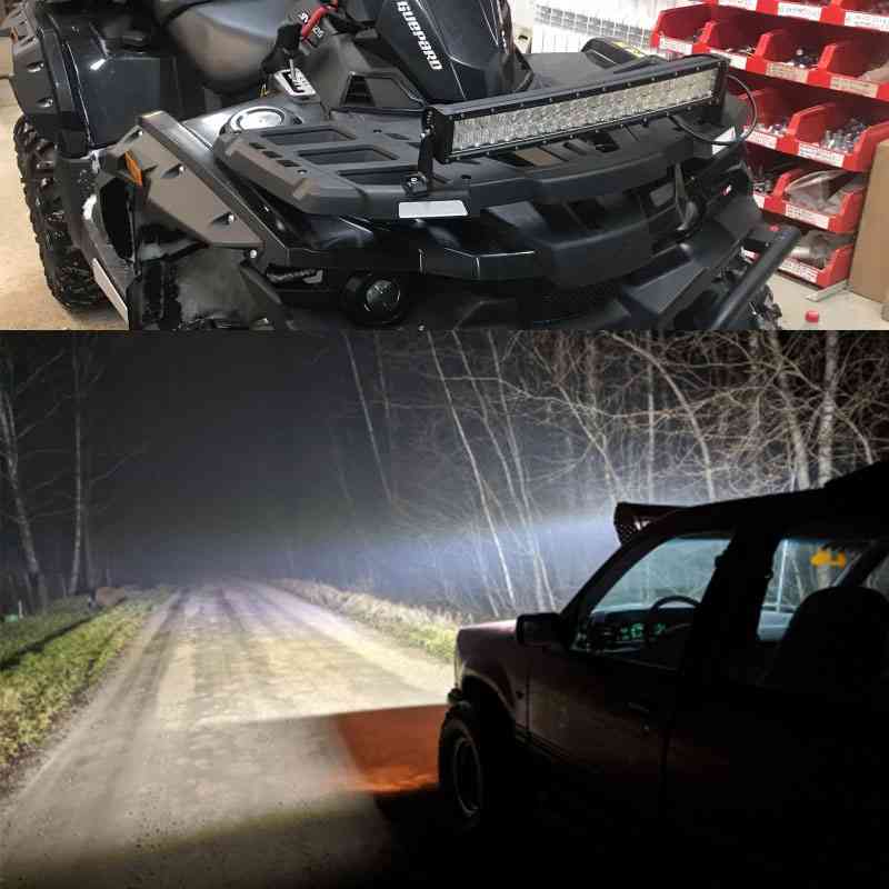
Installing auxiliary lighting transforms nighttime driving visibility. A curved Led light bar offers distinct functional advantages over straight models by matching modern vehicle profiles and casting a wider panoramic beam. However, roof-mounting introduces high-stakes realities. Incorrect installation invites severe water leaks, electrical shorts, and deafening wind noise. Many drivers struggle to bridge the gap between buying high-output lighting and integrating it safely. Modern vehicles utilize complex CAN bus networks and sensitive structural frameworks. You must integrate heavy-draw accessories without compromising safety, aerodynamics, or factory electronics. A poorly executed roof penetration degrades structural integrity, while a compromised wiring setup risks thermal events. This guide provides a definitive, step-by-step technical framework. You will learn how to select durable hardware, execute a weather-tight roof mount, and route the wiring safely to meet strict OEM standards.
Electrical Safety is Non-Negotiable: Utilizing a properly rated LED light bar wiring harness with an appropriate relay and inline fuse is critical to prevent voltage drops and thermal events.
Bracket Geometry Dictates Fitment: A vehicle-specific curved light bar mounting bracket is required to match the exact windshield or roof camber, preventing structural stress and vibration.
Weatherproofing Requires Redundancy: Roof penetrations must utilize a combination of mechanical seals (grommets or rubberized rivnuts) and chemical seals (marine-grade silicone) to prevent cabin water ingress.
Aerodynamics Impact Usability: Improper positioning of a curved roof mount LED light bar creates turbulent airflow, resulting in severe wind whistle and reduced fuel efficiency.
Grounding is the Most Common Failure Point: Establishing a bare-metal chassis ground is mandatory to prevent flickering, relay chatter, and premature diode failure.
Pre-Installation Evaluation: Framing the Curved Light Bar Project
Success Criteria for Roof-Mounted Lighting
A successful installation must meet four strict physical and electrical objectives. You need optimal forward illumination that cuts through dust and darkness. You require zero water ingress into the cabin, even under high-pressure washes or heavy rainstorms. The electrical system must deliver stable voltage under continuous load without overheating the wires. Finally, the physical mount must create minimal aerodynamic drag. Failing any of these criteria renders the setup a liability on the trail or the highway.
Light spread geometry dictates your hardware choice. A curved bar provides panoramic visibility. It pushes light outward into the ditches and peripheral zones, illuminating wildlife and off-road hazards earlier than a straight beam. A straight bar focuses light into a concentrated forward spot, which works well for high-speed desert running but lacks peripheral coverage. Assess your typical driving environment. Tight trails, winding mountain roads, and dense forests benefit immensely from the broad beam pattern of a curved unit.
Assessing Vehicle Compatibility and Roof Camber
You must measure your roofline curve accurately before ordering parts. The light bar radius must match the vehicle's structural profile. Mismatched cambers cause severe bracket stress, which eventually leads to hardware failure or micro-fractures in the light bar's polycarbonate lens.
Park the vehicle on level ground and clean the roof surface.
Hold a flexible straightedge or a piece of string taut across the intended mounting zone from driver side to passenger side.
Measure the depth of the curve at the exact center of the roof down to the sheet metal.
Compare this camber measurement against the manufacturer specifications of your chosen light bar.
Identify potential interference points early. Factory roof racks often block mounting channels or cast massive shadows. Sunroof clearances dictate how far back you can drill without shattering the glass track. Satellite antennas require unobstructed sky views to function. Windshield wiper arcs can contact low-hanging brackets. Map out these physical constraints with masking tape before making any permanent modifications.
Essential Tools and Materials Checklist
An OEM-quality installation demands professional-grade tools. Do not attempt this project with basic hand tools or dull drill bits. You need specific equipment to handle sheet metal and heavy-gauge copper wire properly.
Digital multimeter for continuity testing and measuring voltage drops across the circuit.
Automatic wire strippers to remove insulation without damaging the underlying copper strands.
Titanium step drill bits for clean, burr-free sheet metal penetration.
Heavy-duty rivnut tool with M6 and M8 mandrels for setting threaded inserts into the roof.
Spring-loaded center punch to prevent drill bit wandering on curved sheet metal.
Fish tape or a stiff coat hanger for pulling wires through tight firewall grommets.
You also need specific consumable materials to guarantee longevity. Stock up on marine-grade adhesive-lined heat shrink. When heated, the adhesive melts and seals the connection from moisture. Buy dielectric grease to protect exposed ring terminals at the battery. Automotive-grade TESA tape is mandatory for wrapping interior wire looms to prevent rattling behind the dashboard. Finally, purchase a high-quality rust-inhibiting primer to treat all drilled holes before inserting hardware.
Hardware Selection: Brackets, Harnesses, and Relays
Evaluating the Curved Light Bar Mounting Bracket
Your mounting solution dictates the structural integrity of the entire system. A curved light bar mounting bracket comes in several configurations, each with distinct advantages and load limits. Drill-in roof brackets offer the highest load capacity and are mandatory for heavy 50-inch or 54-inch bars. Gutter-mount clamps avoid drilling but limit weight distribution and can deform the factory drip rails under heavy vibration. Upper windshield or A-pillar brackets provide a sleek, integrated look but often require minor weatherstripping modification and can increase wind noise near the driver's ear.
Material selection directly impacts vibration dampening. Powder-coated steel offers immense rigidity but risks aggressive rust if the coating gets scratched by tree branches. Billet aluminum provides excellent corrosion resistance and dampens high-frequency vibrations effectively, though it costs significantly more. Always integrate tamper-proof security nuts into the bracket assembly. Highly visible roof-mounted accessories attract theft in urban environments. Security hardware requires a specialized keyed socket, acting as a strong deterrent against opportunistic thieves.
Bracket Type
Installation Method
Vibration Resistance
Best Application
Drill-In Roof Bracket
Permanent Rivnuts
Excellent
Heavy off-road use, large 50+ inch bars
Gutter-Mount Clamp
Bolt-on Tension
Moderate
Leased vehicles, temporary setups
A-Pillar / Upper Windshield
Factory Bolt Replacement
High
Clean OEM look, reduced wind noise
Specifying the LED Light Bar Wiring Harness
Electrical fires stem from undersized wiring. You must calculate total amperage to select the correct AWG (American Wire Gauge) thickness. The formula is simple: divide total wattage by system voltage. A 300-watt light bar on a standard 12-volt system draws 25 amps continuously. A standard 14 AWG wire will overheat and melt its insulation under this load. You need a 12 AWG or 10 AWG LED light bar wiring harness to prevent dangerous voltage drops over the long run from the battery to the roof.
Relays keep heavy electrical loads out of the passenger cabin. Instead of routing 25 amps through your dashboard switch, you route a tiny 0.5-amp trigger signal to the relay in the engine bay. The relay then connects the battery directly to the light bar. You need a 40A or 60A relay for high-current switching. A standard 4-pin SPST (Single Pole Single Throw) relay handles basic on/off functions perfectly. Always size your inline fuse 10 to 15 percent above your maximum continuous amp draw. For a 25-amp draw, use a 30-amp fuse.
Total Wattage (12V System)
Continuous Amp Draw
Recommended Inline Fuse
Minimum Wire Gauge (Up to 15 ft)
120 Watts
10 Amps
15 Amp
16 AWG
240 Watts
20 Amps
25 Amp
14 AWG
300 Watts
25 Amps
30 Amp
12 AWG
400+ Watts
33+ Amps
40 Amp
10 AWG
Avoid pre-assembled budget harnesses found at discount auto parts stores. They frequently suffer from relay failure, brittle PVC insulation, and moisture intrusion at the connectors. Custom-built or premium marine-tinned wiring systems offer superior value. Tinned copper resists corrosion in harsh environments, ensuring the wire does not turn green and brittle over time. Investing in premium wiring prevents catastrophic electrical failures down the road.
Executing the Curved Roof Mount LED Light Bar Installation
Positioning for Aerodynamics and Glare Reduction
Placement dictates performance. Mounting a curved roof mount LED light bar too far forward causes severe hood glare. The light spills downward, illuminating the hood of your truck and blinding you at night. Set the bar slightly behind the upper windshield line to use the roof edge as a natural cutoff shield. Alternatively, fabricate a custom glare shield beneath the housing or apply matte black vinyl to your hood to absorb the stray light.
Wind whistle plagues roof-mounted accessories. Cooling fin resonance creates high-pitched noises at highway speeds as air rushes through the aluminum heat sinks. Utilize aerodynamic silencers inserted between the fins to break up the airflow. Rubber dampeners alter the resonant frequency of the metal, stopping the vibration. Adjusting the pitch angle by just two or three degrees often disrupts the turbulent airflow causing the noise without noticeably affecting the beam pattern.
The Structural Mount (Drilling vs. Non-Drilling)
Drilling into a vehicle roof carries permanent implementation risks. You must avoid hitting side-curtain airbags, which are packed tightly along the roofline above the doors. You must also clear factory wiring looms hidden in the headliner. Drop the interior headliner slightly by removing the A-pillar trim, sun visors, and grab handles. Shine a flashlight into the gap to inspect the exact drill zone. Measure three times before making a single hole.
Follow a strict step-by-step protocol for drilling to ensure a factory-strength hold:
Apply masking tape over the mounting area to protect the paint from metal shavings.
Use a spring-loaded center punch to mark the exact hole location, preventing the drill bit from walking across the curved roof.
Drill a small 1/8-inch pilot hole. Wrap tape around the bit half an inch from the tip to act as a depth stop, preventing you from punching through the headliner.
Use a titanium step bit to widen the hole to the exact outer diameter of your rivnut.
Deburr the sharp metal edges immediately with a deburring tool or round file.
Apply rust-inhibiting primer to the bare metal edge using a cotton swab. Let it dry completely.
Compress the threaded inserts using a dedicated rivnut tool until they sit flush and tight against the sheet metal.
Weatherproofing Roof Penetrations
Water ingress ruins interiors, shorts out electronics, and causes mold. Weatherproofing requires an exact sequence. First, install rubberized rivnuts or specialized waterproof roof glands for the wire pass-through. Never rely on metal-to-metal contact to keep water out. Second, apply a generous bead of UV-resistant marine sealant around the penetration. Sikaflex 221 or 3M 5200 are industry standards for permanent, waterproof adhesion.
Apply the sealant under the bracket base, insert the bolt, and torque the bracket bolts to the manufacturer's specification. Do not over-tighten. Crushing the mechanical rubber seal causes it to split and fail prematurely. Wipe away excess sealant with rubbing alcohol before it cures. This redundant sealing strategy ensures the cabin remains completely dry during heavy rainstorms and high-pressure car washes.
The Wiring Process: Routing and Electrical Integration
Cable Routing from Roof to Engine Bay
You must route the heavy gauge cable down to the battery safely. Evaluate your routing paths carefully. Running wire down the windshield weather stripping is common. You pull back the rubber molding, lay the wire in the ditch, and secure it with dabs of black automotive silicone before replacing the molding. Passing wire through a drilled waterproof roof gland offers the cleanest look but requires another hole in the roof. Routing along an existing roof rack channel provides excellent physical protection and keeps the wire entirely out of sight.
Mitigate wire chafing aggressively. Vehicle vibrations will slice through standard PVC wire insulation against bare metal edges. Utilize braided wire looms for maximum abrasion resistance. Secure the loom with UV-rated zip ties or rubber-cushioned P-clips every six inches. Always ensure drip loops are present. A drip loop is a deliberate downward U-shape in the wire just before it enters the cabin or roof gland. Gravity forces water to run down to the bottom of the loop and drip off, rather than traveling along the wire into the vehicle.
Engine Bay Connections, Relays, and Flawless Grounding
Disconnect the negative battery terminal before starting engine bay work. Connect the main power ring terminal to the positive battery post. Ensure the inline fuse holder sits within six inches of the battery. This protects the entire length of the cable. If the wire shorts out against the firewall, the fuse blows immediately at the battery, preventing a fire.
Mastering the chassis ground prevents most electrical gremlins. You must sand away factory paint to expose bare metal for the ground connection. Use a star washer between the ring terminal and the chassis. The star washer bites into the metal, ensuring a low-resistance connection. Poor grounding causes flickering, relay chatter, and premature diode failure. Once the bolt is tight, coat the entire connection in dielectric grease to prevent rust from forming on the bare metal.
Mount the relay strategically. Keep it upright to prevent water pooling inside the casing. Mount it high on the firewall, away from extreme exhaust manifold heat. Ensure it remains shielded from direct road spray coming up through the wheel wells. A wet relay will short out internally and leave you without lighting on the trail.
Cabin Switch Installation and Modern CAN bus Integration
Locate an existing factory firewall grommet, usually where the main wiring harness passes through. Carefully pierce a small hole in the rubber membrane to pass the switch trigger wire into the cabin. Use a stiff coat hanger to fish the wire through. If no grommet exists, drill a new hole and install a sealed rubber grommet. Never pass bare wire through a metal firewall hole; the sharp edge will slice the insulation and cause a dead short.
Modern vehicles require ignition-switched power to prevent dead batteries. Use an "Add-a-Circuit" fuse tap in the interior fuse box. Grab your multimeter and probe the fuses with the key off. Find one that reads 0V. Turn the key to the accessory position. If that same fuse now reads 12V, you have found an ignition-hot circuit (often the radio or windshield wipers). Tap into this circuit and route the trigger power to your rocker switch. This ensures the light bar cannot drain the battery if left on accidentally after you park.
Wiring the rocker switch requires attention to pin layouts. A standard 5-pin switch features connections for Power In (from the fuse tap), Load Out (to the relay pin 86), Ground (to the chassis), Dash Illumination (tapped into the factory dash light circuit), and Indicator Light Ground. Follow the wiring diagram exactly. Use insulated female spade connectors and crimp them tightly for a secure fit.
Testing, Compliance, and Long-Term Maintenance
System Testing and Troubleshooting
Execute a strict protocol for initial power-on. Reconnect the negative battery terminal. Turn the ignition on. Flip the cabin switch. Listen for an audible click from the engine bay relay. This confirms the trigger circuit works. Walk to the front and verify all diodes illuminate evenly across the curved board.
Measure voltage drop at the light bar connector using your multimeter. Put the red probe on the positive wire and the black probe on the negative wire while the light is running. The voltage should closely match the battery voltage (around 12.6V to 13.8V depending on if the engine is running). A significant drop (e.g., reading 11.2V) indicates an undersized wire or a poor connection. Inspect the beam for flickering. Flickering almost always points to a compromised chassis ground or a loose ring terminal at the battery.
Legal Compliance and On-Road Usage
Department of Transportation (DOT) regulations strictly govern auxiliary lighting. It is illegal to operate high-output off-road lights on public highways. These bars lack the sharp cutoff lines of DOT-approved fog lights and will blind oncoming traffic instantly, causing severe accidents. Familiarize yourself with local jurisdiction rules regarding uncovered auxiliary lighting.
Many states require opaque snap-on covers for street legality. If the bar is uncovered, police can issue citations, even if the light is turned off. Purchase hard plastic covers that snap securely over the polycarbonate lens. Keep them installed during all highway transit. They also protect the lens from rock chips and UV yellowing during daily driving.
Post-Installation Maintenance
A roof-mounted system requires routine checks. Vehicle vibrations loosen hardware over time. Re-torque all bracket bolts and roof rivnuts after the first 500 miles of driving. Check the roof penetrations for any signs of sealant cracking or peeling. Reapply marine silicone if you spot any gaps.
Inspect the lens for internal condensation after heavy rain. Minor fogging usually clears up as the bar heats up and the internal moisture evaporates through the Gore-Tex breather valve. Heavy water pooling indicates a failed breather valve or a cracked housing seal, which requires warranty replacement. Finally, check the harness terminal connections at the battery. Clean off any white acidic corrosion with a wire brush and reapply dielectric grease annually.
Conclusion
Calculate your specific amp draw using the total wattage of your lighting system to determine the exact inline fuse and wire gauge required for safe operation.
Inspect your vehicle's firewall to locate an existing factory grommet for routing the switch wire into the cabin without drilling new holes.
Gather titanium step drill bits, marine-grade silicone, and a heavy-duty rivnut tool before beginning any roof modifications to ensure a watertight seal.
Measure your roofline camber with a flexible straightedge to confirm compatibility with your selected mounting brackets before ordering hardware.
FAQ
Q: Do I need a special wiring harness for a curved LED light bar?
A: The curved shape does not dictate the harness type. Total wattage and amp draw determine your requirements. You must select a harness with the correct wire gauge, relay capacity, and inline fuse rating to handle the continuous electrical load safely.
Q: How do I wire my light bar so it only turns on with the ignition?
A: Use an Add-a-Circuit fuse tap in your interior fuse box. Tap into a circuit that only receives power when the ignition is active, such as the radio or wipers. Route this power to your switch. This prevents accidental battery drain when the vehicle is off.
Q: How do I stop my curved roof mount LED light bar from whistling?
A: Whistling is caused by cooling fin resonance and turbulent airflow. Insert rubber dampeners between the rear heat sink fins to alter the vibration frequency. Adjusting the mounting angle slightly or installing an aerodynamic cover can also disrupt the airflow causing the noise.
Q: Where is the best place to mount a curved light bar on a roof?
A: Mount it slightly behind the upper windshield line. This placement aligns the bar with the roof's natural camber. It balances forward light projection while minimizing severe hood glare that can blind the driver during nighttime operation.
Q: Can I install a curved light bar mounting bracket without drilling?
A: Yes. You can utilize gutter mounts, clamp onto existing roof rack crossbars, or use specialized magnetic mounts. However, non-drilling alternatives have strict load limitations and lower speed ratings. They are generally not recommended for heavy 50-inch bars.
Q: Why is my LED light bar flickering after installation?
A: Flickering is typically caused by a poor electrical connection. The most common culprit is a weak chassis ground over painted metal. It can also result from an undersized relay struggling to hold the load, or a loose ring terminal at the main battery connection.
Q: What size inline fuse do I need for a 50-inch curved LED light bar?
A: Divide total watts by system volts to find the amps. For example, a 300W bar on a 12V system draws 25 amps. Size your fuse 10 to 15 percent above the maximum continuous amp draw. In this case, a 30-amp inline fuse is required.
Shenzhen Creek Optoelectronic Technologies Co., Ltd. produce Car LED work lights, off-road LED light bar, forklift safety lights, agricultural tractor work lights, LED strobe and beacon lights, car radios, etc.